After lighting the heaters and turd, and getting the 228E running (see above link for new update), I reglued an old cutting board that my wife uses for a lap board on our couch. Then I turned my attention to the street side wall again.
After pulling the weights and spacer blocks off of the “last” two blocking glue-ups, I could see that the spacer blocks had made slight impressions in the freezer paper.
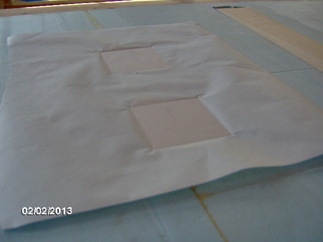
There was a little squeeze out and some slight push up on the upper cabinet block (shown here upside down, with the push up evident by the dark line on the left of the closer block in this pic)
You can see the glue squeeze out a little better here.
I’m starting to wonder if the variation in temperature, and not just the moisture, is contributing to the degree of expansion of the GG. Seems like it should be obvious, but I have not been able to zero in on the ideal application of the GG. Oh, not to worry. I am confident that the joints are strong. It’s just that I would like to get the best of the filling properties w/o having to suffer the extra work of fairing everything back down again.
I shaved the high glue spots down a tad with the small Sureform and finished up fairing the foam and block with the larger homemade hand block with course belt sander paper.
Over the last several days I have been studying up on the hatch strut threads, including some recent newbie threads and Aggie Tom’s, Angib’s, and Grant’s comments on gas struts. I now understand that they are quite different to the linear actuators than I had previously thought due to the fact that they apply constant force (whereas the actuators are switched on and off). Because of this, they want to go from being about perpendicular to the hatch-to-hinge line when fully open, to being in line with the hinge pin (or just a little past, for positive closure) when closed. Otherwise, if configured straddling the dwell point, like I have been saying, they would tend to try to open the hatch when you are trying to close it and get it latched. So you will have to do most of the lifting at first.
I looked at McMaster-Carr and started with the longest throw of the steel struts w/ ball studs first (the stainless steel ones sound really good, but are 10x the $$$). However, Aggie Tom suggested that selecting a style that has lots of power ratings would be a good bet, and the longer throw units are only available in 50 lb. increments, I started to look at the next longest throws with finer steps in weight ratings. (Sorry, the specs are at my desk and I don’t feel like looking them up again at the moment.)
Anyway, I did a few iterations of CAD sketches last night to try and figure out where the blocking would need to go for these struts, but ran out of time before settling on anything concrete.
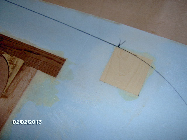
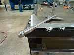
So I waffled a bit on what to do next and ended up doing a test to see where the screw holes would land when using the Kregg to screw the wall sill down to the floor. In the following pic you can see where I used the Kregg to drill into a 1-1/2 thk test block (representing the wall and wall sill). I split this test piece open on the table saw and shaded the hole in with ink so that it would show up in the pic. The little block on top is to help visualize where the wall sill ends and the foam begins. You can then see how far up into the foam the counter bore from the Kregg will be into the foam.
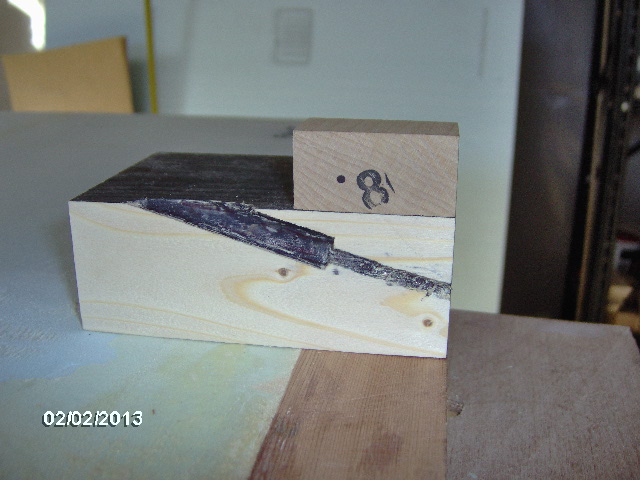
Hmm, contemplation. How do I cover the wall in the flat and then screw it to the floor w/o putting holes thru the canvas? For now I’m thinking that I have to apply the canvas just down to a point above these counter bores, leaving the lower portion of the canvas and the part that will wrap under the floor free, then screw the wall to the floor, fill the counter bore holes, then glue the canvas down the rest of the way and wrap under the floor.
So next I got the side profile templates out again and knocked off the little flashing from the CNC router using the small sanding bock (I seem to use that tool more than anything else!).
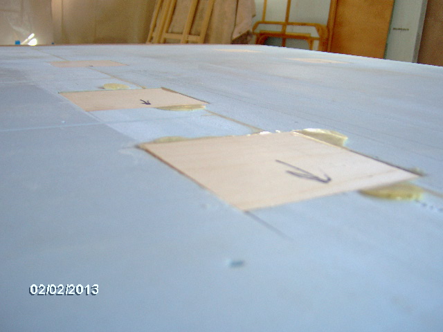
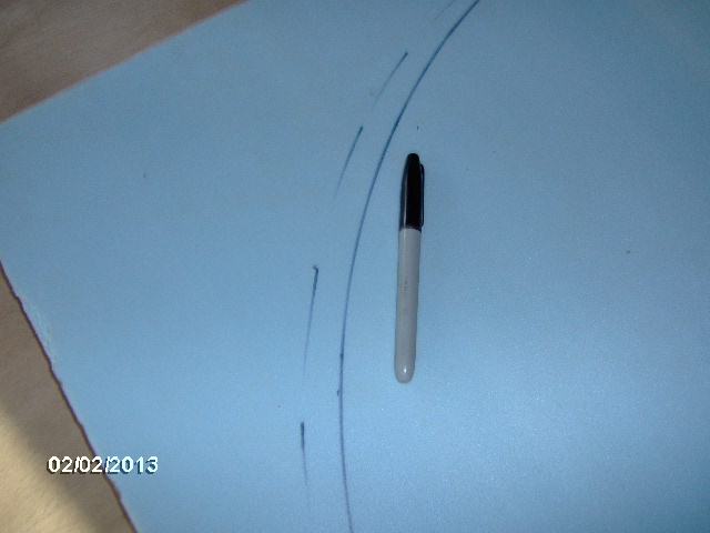
Then I fit the templates to the wall again and used a sharpie to roughly trace the good arcs onto the foam, and to mark the starting and stopping points for the gentle roof arc portions (the ones that were inverted by the CNC).
Then I removed the templates and used the good part of the arc on the center template section, placing it tangent to the previous marks, and traced the rest of the ceiling arc on the missing sections. If this is confusing, look up a few posts to the part where I noted that my templates had not come out correctly, and where I said that this would make more work for me. I was right.
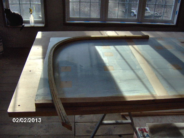
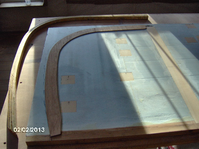
Then I put the templates back down for some pics to show the deviation. Here is a long shot from the end of the “table” looking from the galley end toward the front.
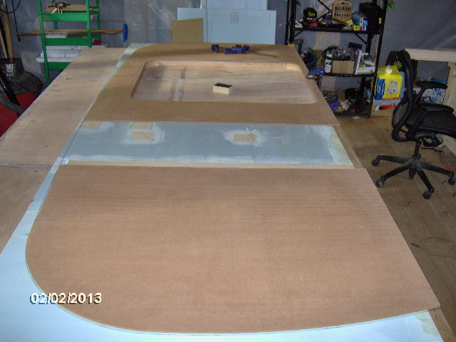
I couldn’t resist climbing up on the bench to take another shot of the overall layout.
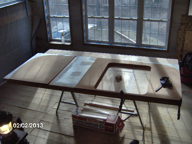
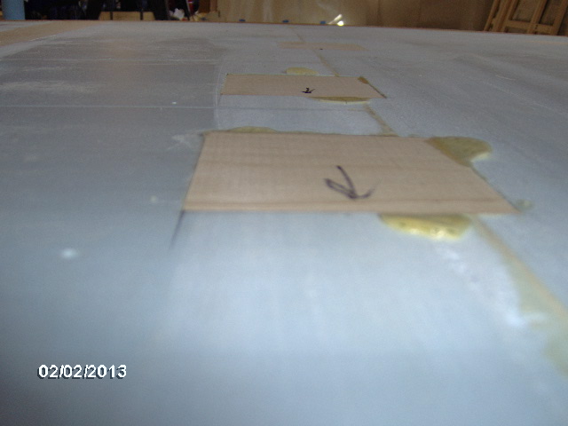
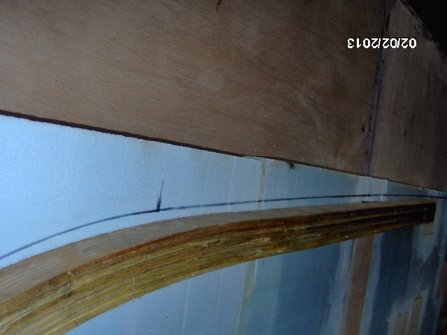
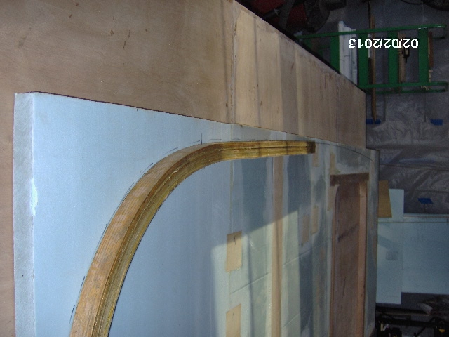
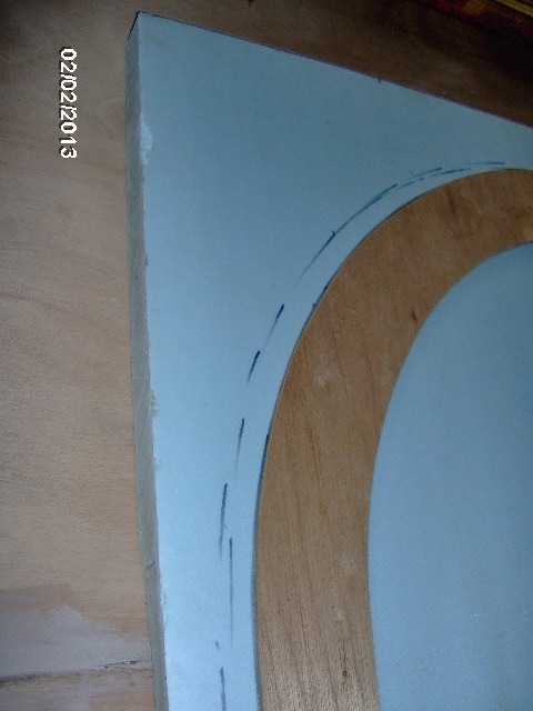
In these next few pictures I took them from around the table/floor, but have rotated them here to try and simulate the installed situation better. This is looking from the galley up along the roof line. The rough outline is about 1/8 inch bigger than the template due to the sharpie being dull and the thickness of the nib on the pen, but you can clearly see the larger gap where the template dishes where the correct ceiling outline bows up.
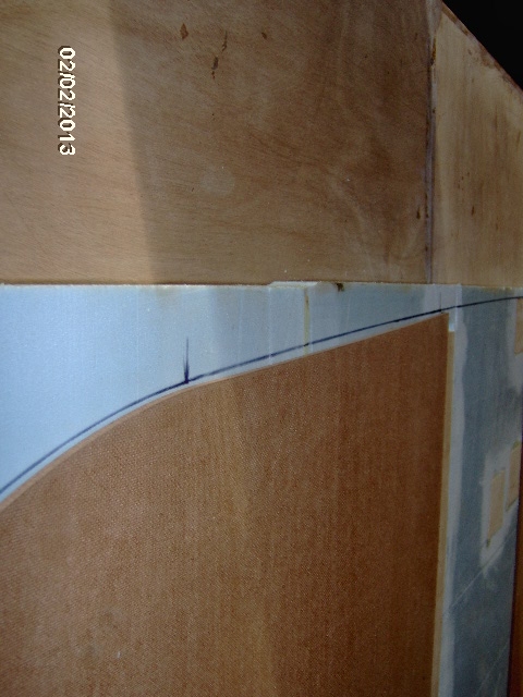
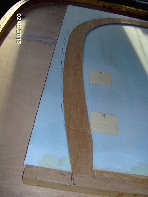
This is from the front, looking back at the inside of the street side wall where you can see the correct outline of the ceiling vs. the dished front template and the correct (but short) middle template.
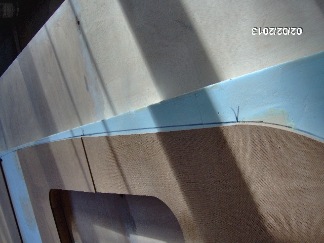
The factory imprint on the back of the flake board with the oblique sunlight made a nice optical shadow effect in the picture.
Here you can see how the block at the top of the front cabinet will be cut.
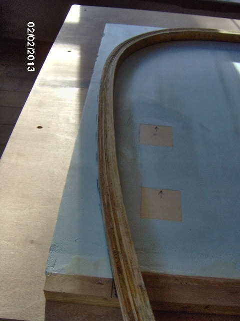
Next I took one of the laminated galley wall edgings and laid it onto the tracing to see how well (or poorly) it lined up. Remember I had laid these out by hand before I had gotten the templates in hand.
At first I put the tightest part of the curve (the upper rear) tangent to the sharpie line and checked to see how far out the top and bottom were. Here is the bottom; not great.
Here’s where it is tangent at the top rear.
And here is looking forward along the top. No bueno.
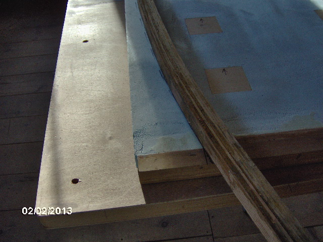
Next I moved the edge piece so that it was covering all of the tracing and traced its outer edge (dashed line) so that I could get an idea of how much it would be thinned if I were to glue it in and trim it to the template.
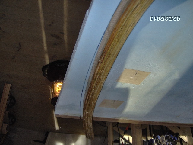
Here’s a long shot of the edge piece laying on the wall (Simon supervising from the window ledge).
I fudged this around a couple of different ways trying to optimize the fit.
Then I laid the hatch rib template down and found that it was pretty spot on (also made by hand prior to getting the CNC templates). Hmm?

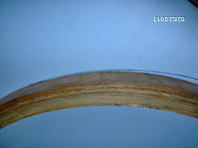
It turns out that the laminated wall edgings no longer match each other. They must have swelled or shrunk (or at least one of them did) so that they (one?) no longer matches the profile. (I did not check them both against the layout, but they had matched each other very well when they came out of the form and no longer do.) I now need to decide whether I keep going with these (which also have other issues, as mentioned way back), or to make up new ones from segment joined lumber.
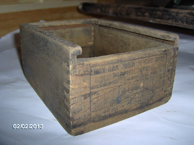
Other projects tackled today were to true and re-glue a cutting board for my wife, and these little wooden boxes that I got from a clean out at work. The larger one is somewhat crude; just joined with small box nails, but the smaller one is much cooler with finger jointed sides, a dado slot for a lid (missing lid) and embossed labels on each end for “REX AAA HIGH SPEED BITS”, “HARDENED”, with boxes for “NUMBER OF BITS”, “SIZE” and “WEIGHT”, then “READY FOR USE”.
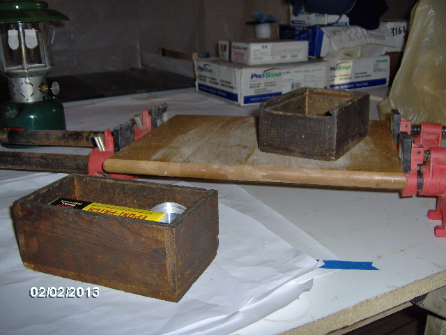
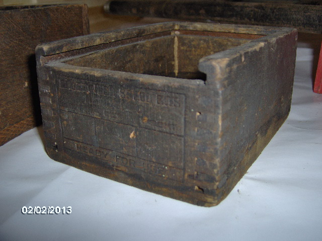
They were horribly grimy from years of being exposed to the cutting oil environment of a machine shop, so I hit the bit box with some greenie pad to remove a bunch of the grime w/o ruining the age old patina.
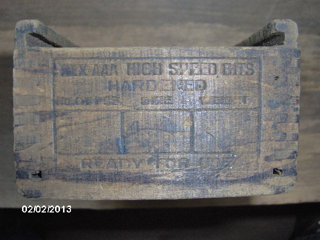
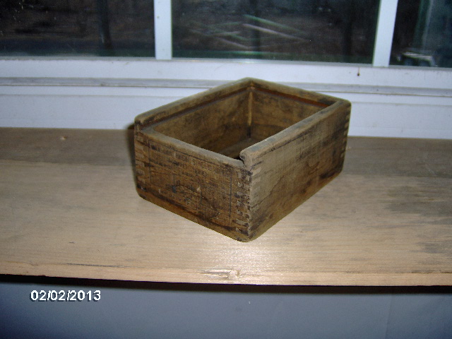
Although I am not going for the rustic theme on TPCE, I thought this would be a nice touch and would maybe be a good box for keeping strike-anywhere-matches, or maybe lantern mantles and such.
That’s it for now. Tomorrow will be a chunker work day.


 Sure must be Nice to have a Heated indoor Shop !!!!


 I’ve seen the shows ...BIG MONSTER SCARY Machines Indeed !!!


 ). Unfortunately, two years ago one of the spotters was seriously injured when he launched his quad off of the berm of the service path that runs out through the field. The field is so flat and level and is camouflage to itself, that the slight rise at the path was not as visible to the spotters as it should have been, and he hit it unexpectedly at high speed. The insurance rates went way up, we all have to sign additional waivers, and they now place markers all along the berm so that the spotters can see the path better, plus all of the other safety requirements that are prerequisites to play (hard hats, safety glasses, fire extinguishers, first aid kits, hydraulic hoses in good condition, state boiler/pressure vessel inspections for the air cannon tanks, etc.).