Thursday, the brown truck cometh.
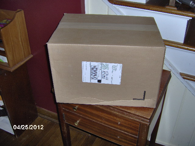
And I was not shocked to see...
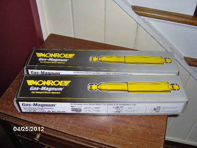
Shocks.
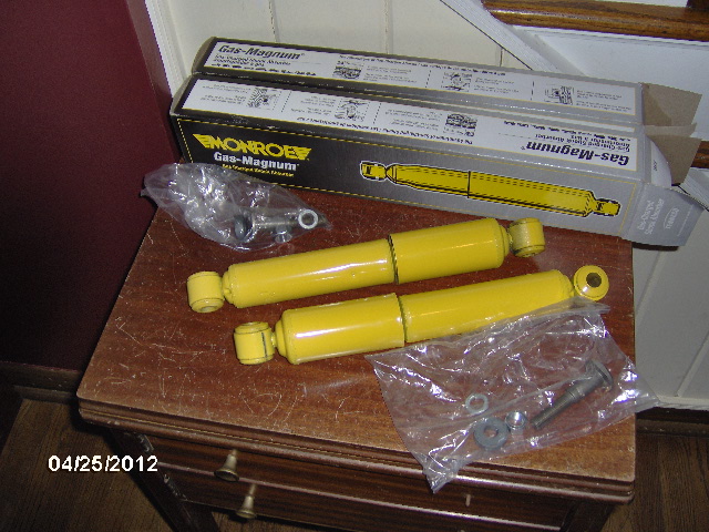
With one shock mounting stud and associated hardware per.
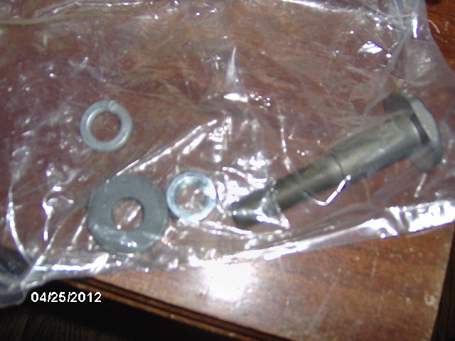
Once I pulled open the ends of the cartons they weren't going to close back up well, and I didn't want to loose anything so I left the hardware in the bags for now.
Friday: The shock mounting stud on top is the one that came with the shocks. It is a round head shoulder bolt with a pair of wrench flats on the sides of the head and a thick washer that fits over the threaded portion but not the shaft portion, thus setting the compression stack height of the shock bushing.
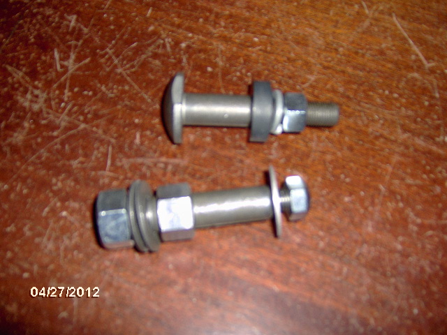
The one on the bottom is one that I picked out of a box of odd shock mounting studs that they had behind the counter at my local auto parts store. I picked it because it was unplated (easier to weld on it if I decide to), it has a heavy 5/8-18UNF thread on the mount end with hex shoulder, and it still had a bar code with part number label on it. The later allowed the parts guy to identify it as being obsolete, but he was able to find old stock at another store that would not cost me any shipping to bring in. The other likely candidates in the box were also singles but were either plated, odd configurations (or both) and/or did not have part info. Wanting to keep things moving along, and since it was closing time at the store, I bought the one he had (add $4.75 to the tally), and asked that they confirm the inventory at the other store (in NJ) and I would check with them today (Saturday). If push came to shove I could work off of the one I had in hand, even making a duplicate if I had to, but that turned out to be unnecessary since when I called today to check they had found it in stock and were having it sent up. Should be here by Wednesday, latest. Store is right on my path home from work.
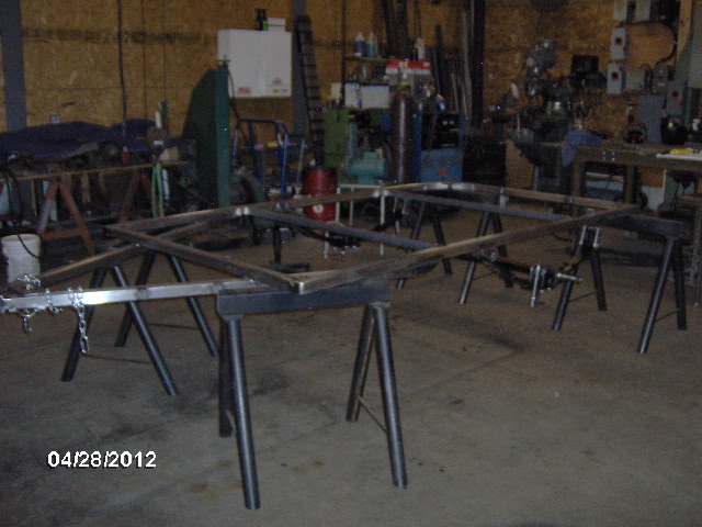
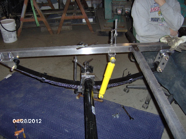
Saturday: I had thought that we would be working on the Rover this weekend, even tho Rover Mike was not going to be there, but it turns out that his Rover 4x4 fab expert was also not going to be there, so Yippee!!! I got to do trailer fab. While I was noodling and fussing with some long hand math trying to figure out the shock travel vs. spring travel, Karl swung the frame over, I helped him lay it right side up on the saw horses, and we mocked the springs, axle and U-Bolt plates back into place.
While I had the camera out, I took a shot at some equipment that Karl had picked up from a welding shop that was updating their equipment. This is a rotary positioning table.
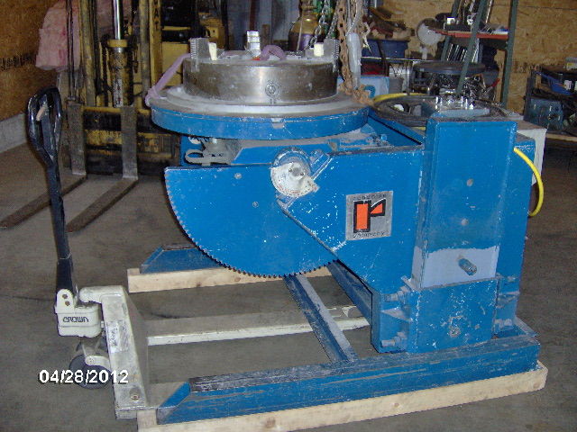
Note the pallet jack in front for scale. It weighs 2900 lbs and the three jaw chuck looked to have at least an 18 inch capacity. The load handling capability is a ridiculous 56k lbs. He bought it way under value and has already flipped it to cover the cost of this new/used TIG welder set up. I want to say it has 350A capacity, pulse arc, cooler, pedal, leads, torch, and a really well made wheeled cart.
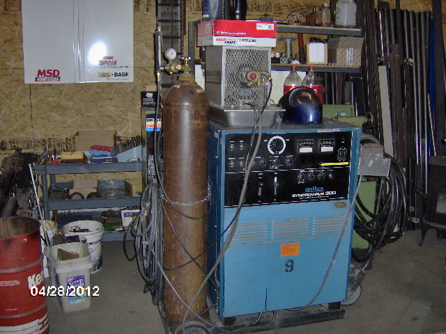
Welds really nice, too. A real workhorse.
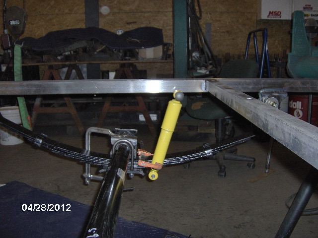
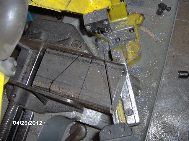
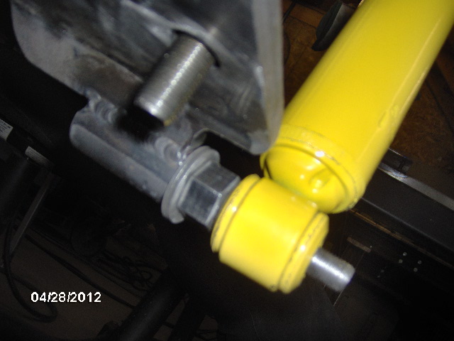
Based on some measurements and my calculations the springs will compress about 4-1/2 inches at their rated load capacity, and the shock has 4-1/4 inches of travel, so the shock would need to be laid over at an angle of just over 2 inches difference from top eye to bottom eye to match that travel (i.e. if the shock is in the same axis as the spring it is a 1:1 ratio, but with the shock laid over slightly, upper eye behind lower eye, say, relative to the vertical motion, then the travel is scaled by approximately the ratio of the adjacent side of the triangle to the hypotenuse. A little long hand Pythagorean formula and square root math and I figured that the upper eye would need to be located about 2-1/16 inch or more behind the lower eye. I had an idea of how I thought I could mount the shock studs, so I did a little mock up to see how that might look.
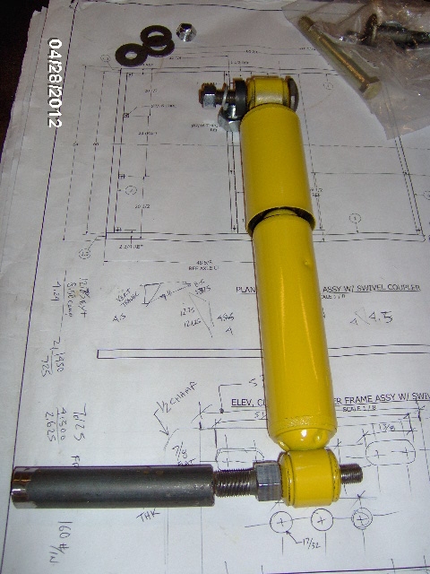
The piece next the lower stud is 1 inch round bar.
I wanted to keep the upper mount as close to the frame rail as practical to avoid cantilevered loads and twist on the rail, since I had no plan for a dedicated shock mounting xmbr. I taped a hex nut onto the shock body with electrical tape to act as a 3/8 inch thick spacer and lightly clamped the shock body to the spring in the approximate final location. The clamp had rubber pads on the jaws to further guard against squashing the shock body.
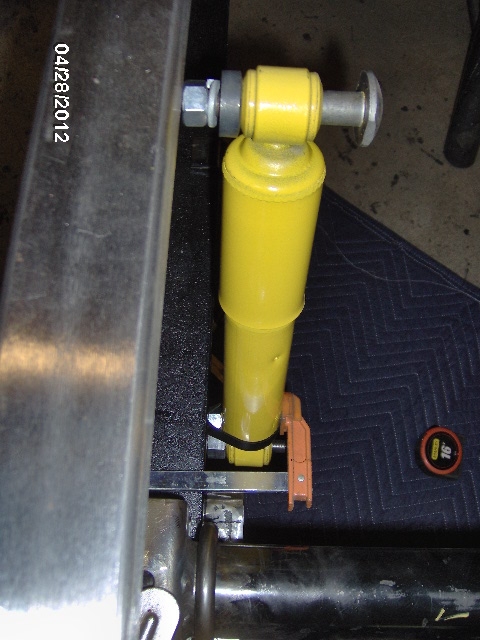
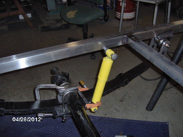
After a bunch of measuring using a framing square I decided that I could get the desired clearance with the spring by setting the upper shock mount face 1-1/8 inch in from the inside of the frame and notching the inside rear corner of the U-Bolt plates slightly to clear the lower shock eyes. The 2x3 x 3/16 wall rectangular tube left over from the little front swivel sleeve xmbr would work perfectly for the upper mounts and I knew exactly where that piece was... sitting inside the driver's side seat riser of the Land Rover... in Mike's cargo trailer... behind the shop.
I can't squeeze thru there, certainly not with those extra storage bins mounted above the trailer fenders.
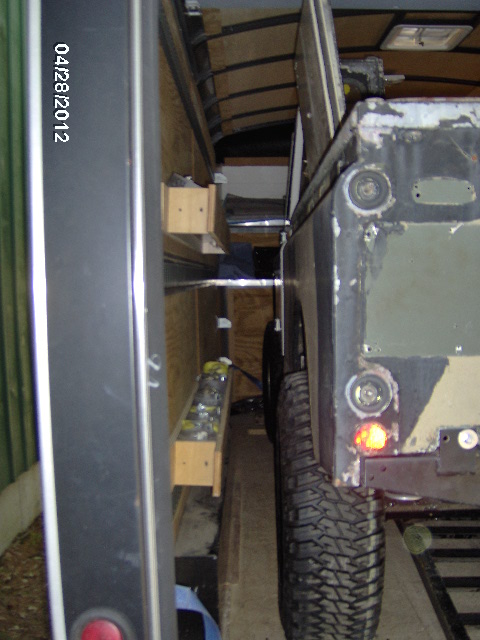
And I couldn't climb thru the bed because the super thin light weight roof cap was flipped upside down and was lying on its drip rails on the bed rails.
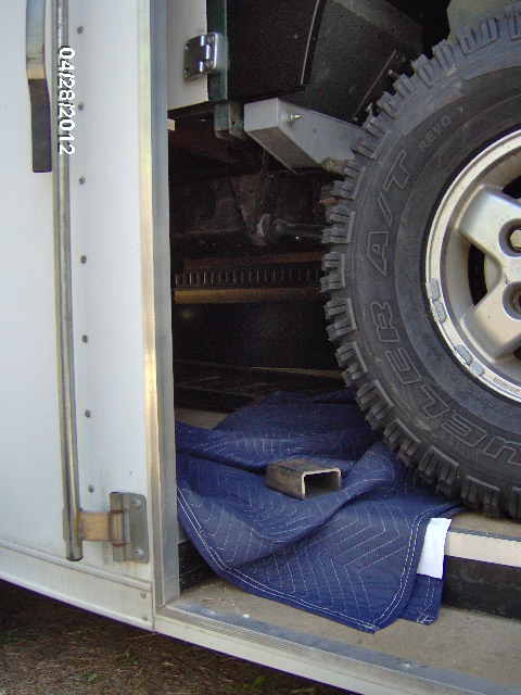
Now I've been able to get into some pretty tight spaces and awkward positions while working on submarines, so this shouldn't be that hard. I laid a moving blanket down under the truck from the curb side access door, squeezed between the front tire and door jamb, and climbed in under the truck. When I got to the driver's side I had to prop my elbow up on the trailer's inner fender in order to make the turn to stand up. Nothing to it, piece was right where I thought it was.
The piece was short enough that I would have to miter each end before parting them off, or I wouldn't have enough to hold them in the saw, so I first had to square the end off from where I had cut the little front swivel sleeve xmbr.
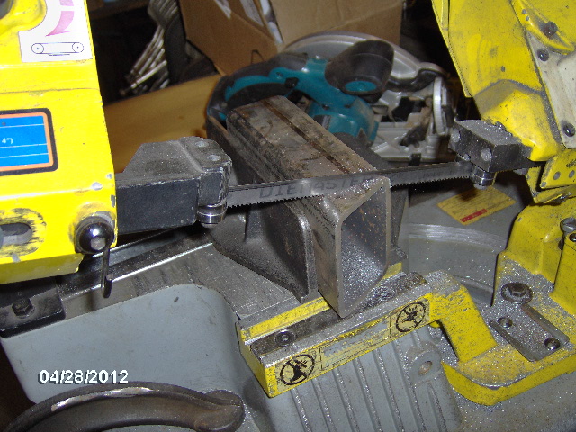
Then after a little layout, I cut the first miter, holding back 3/4 inch from each of the final edges.
Then miter the other side.
Then part them off.
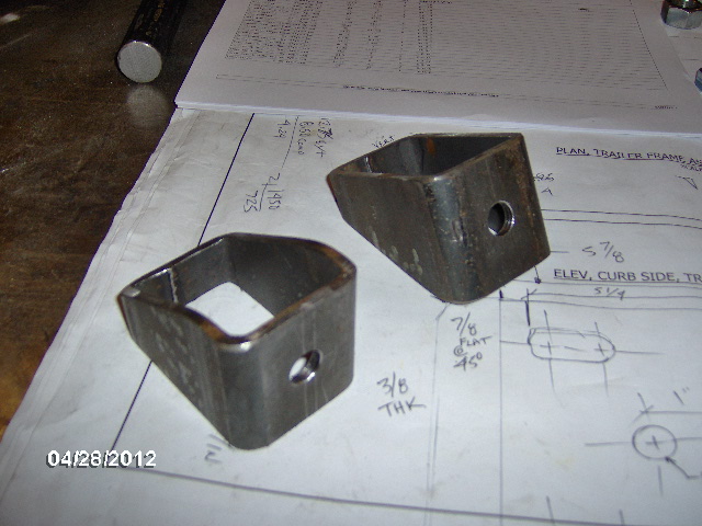
A little more layout work and some drilling in the milling machine.
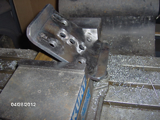
Deburr the holes, chamfer the edges and roll the corners a tad on the sander and here you have two upper shock mount brackets.
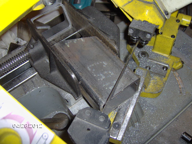
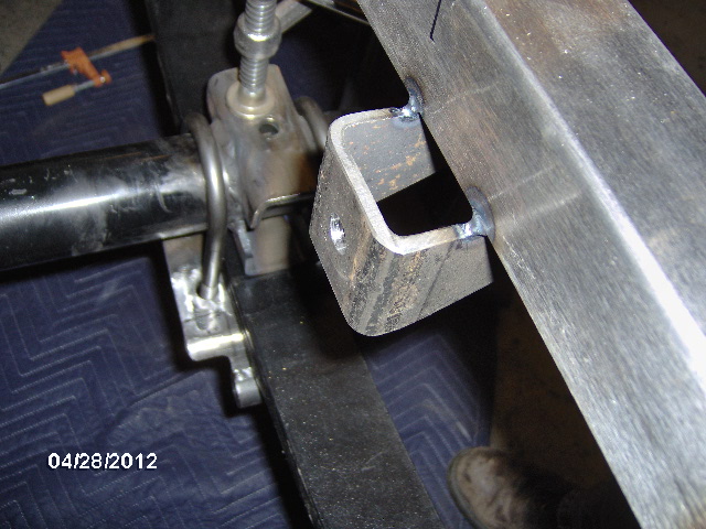
And here is one of the upper mount brackets mocked into place.
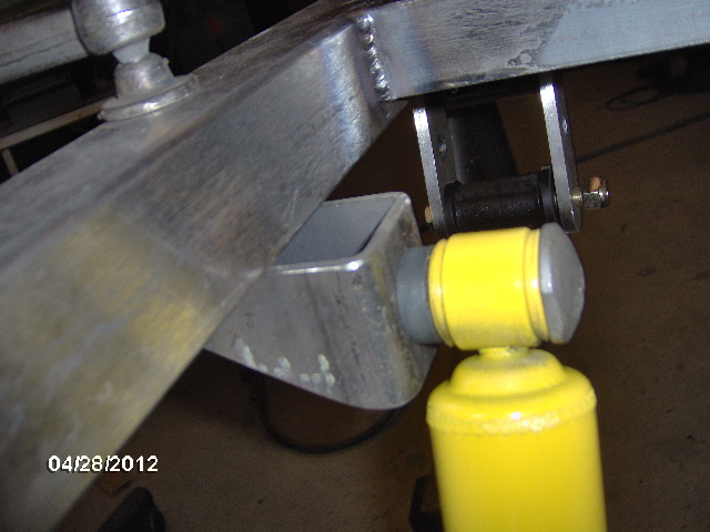
By using the 2x3 rectangular tube, I could get the 1-1/8 inboard spacing while still tying back to the outside face of the frame rail.
I will probably trim some of the excess threads off of the shock mounting stud before final assembly. I'm going to leave the bracket open like this, rather than box it in and make a place for junk to settle on top.
Karl didn't have a 5/8-18UNF tap (guy's got NO tools...geez


) so I popped out for a spot of lunch and ran down to work

to borrow one, plus the 37/64 inch pilot drill (that I sharpened on the Drill Doctor).
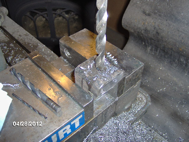
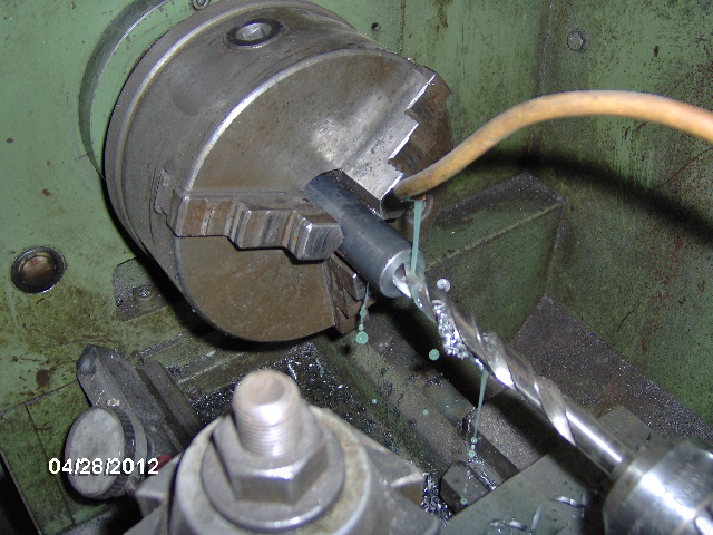
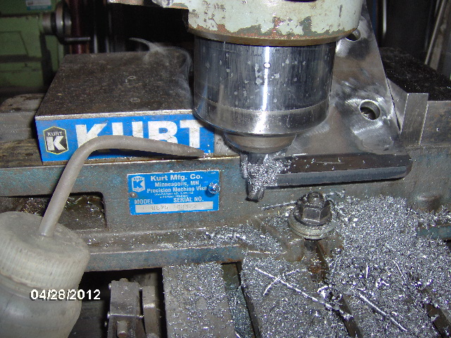
Drilling out the 1 inch round bar for the lower shock stud.
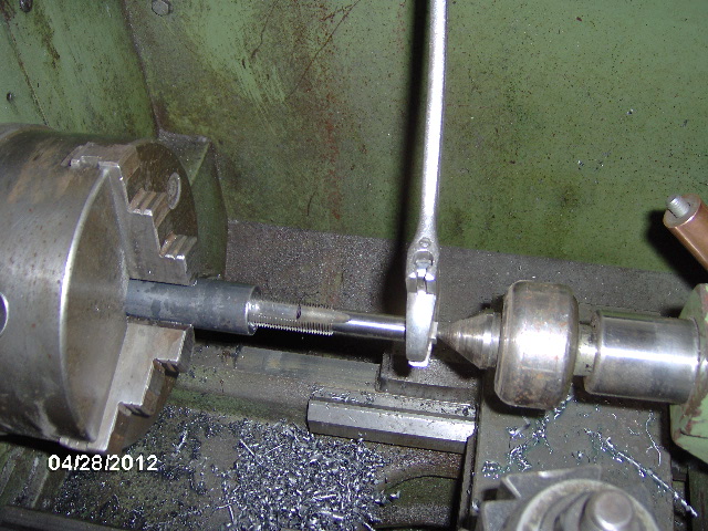
Here I am hand tapping in the lathe, but I am using the live center in the tail stock centered in the shaft end of the tap to keep it perfectly aligned while starting.
Meanwhile, Karl was setting up the U-Bolt plates to notch them in the mill (I would have just nipped them with the cut off wheel, but this would make a nice radius in the corner.
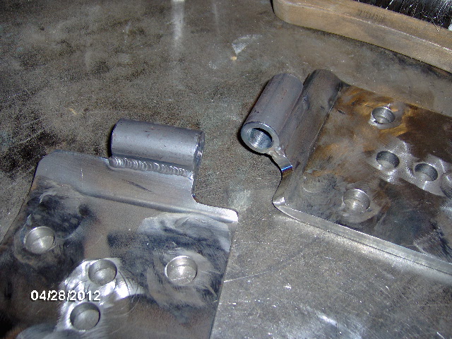
Wash, rinse, repeat, part the lower mount in the saw, touch everything up on the sander (no pics), and shim them up on the bench for a little fit check.
The thin flat washers are just there to make up for where the thread runs out under the hex portion; split lock washers and blue thread locking compound will be used at final assembly.
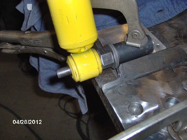
Use the new TIG welder for the first time, chase the threads again after welding, and you get custom threaded lower shock mount U-Bolt plates.
Now I could fit the U-Bolt plate in place, positively locating the lower shock eye and decide where along the frame rail to put the upper mount bracket.
Much noodling and discussion followed about whether to allow the shocks to limit axle droop while hedging against bottoming out on compression, or having a limited amount of remaining travel under full capacity loads. With the axle as it was with no hubs and no wheels/tires I could pull it down a bit further, perhaps 3/8 - 1/2 inch. Karl reasoned that this would be the least concerning action, the relatively light axle assembly dropping away while under extension dampening (I agreed). On the other hand, it would be nice if the shock were only compressed about 1/4 to 1/3 of its travel by the empty weight of the camper at ride height leaving more travel in store for compression (as it was now I figured it would be in the middle of the range when the dry/empty weight was applied). In the end we reasoned that the calculations that I had made matched the expected axle travel as closely as I could figure without knowing the final dry and loaded weights precisely, and that, although my guesstimated final all up max travel weight would put the shock to within 1 inch of full compression, there will be plenty of room remaining between the bottom of the frame and the upper axle perches to fit a suitable bump stop. All else fails, if it doesn't work out right I can remove and rework the U-bolt plates, raising or lowering the lower mount as necessary to suit these shocks better, or for longer shocks. Day light's wasting and this thing needs to get straightened and go to paint.
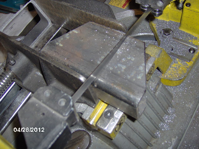
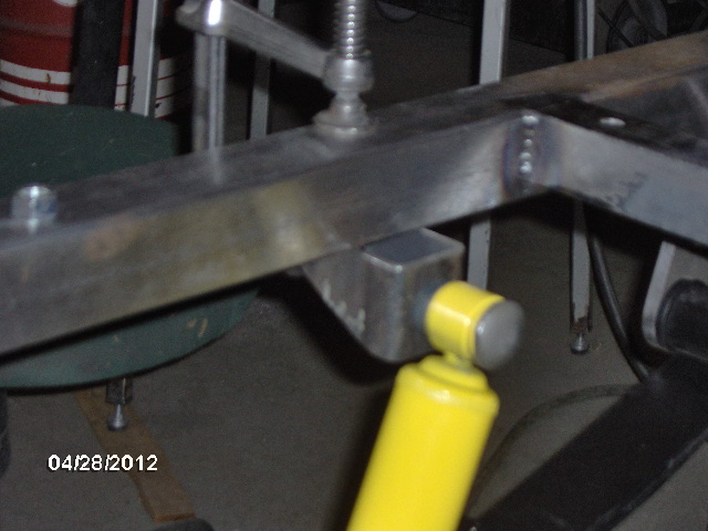
Here's a misleading camera angle from underneath not showing the shock clearance at the U-Bolt plate notch well at all.
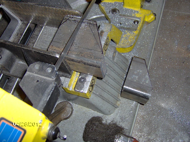
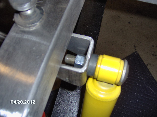
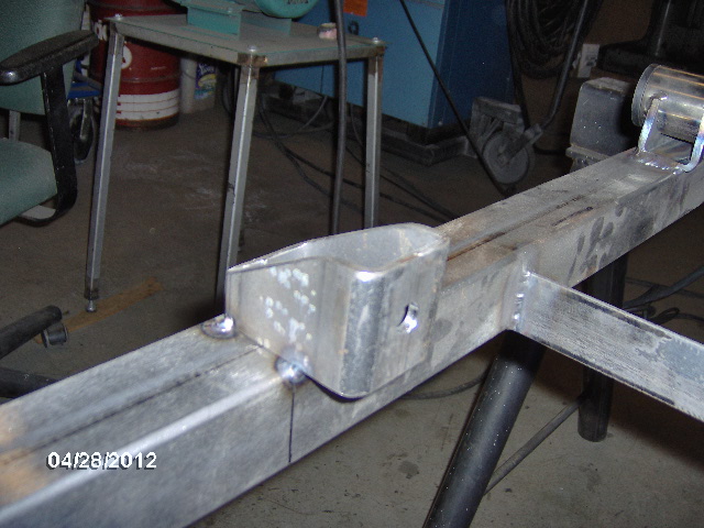
And here's the curb side upper mount in the foreground tacked in place with the lower mount/U-Bolt plate notch beyond.
And another view of the tacks from underneath (Karl seemed anxious to play with his new welder, so I encouraged him to weld this up).
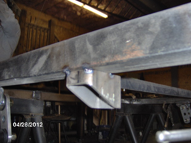
You can also see how the 3 inch bracket ties into the outside wall of the frame.
And another pic of the same thing after we stripped the leaf springs and axle back off, and flipped the frame back over for welding.
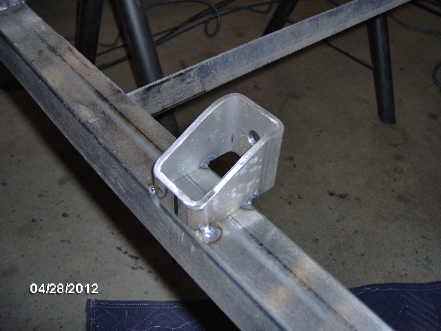
And the other side.
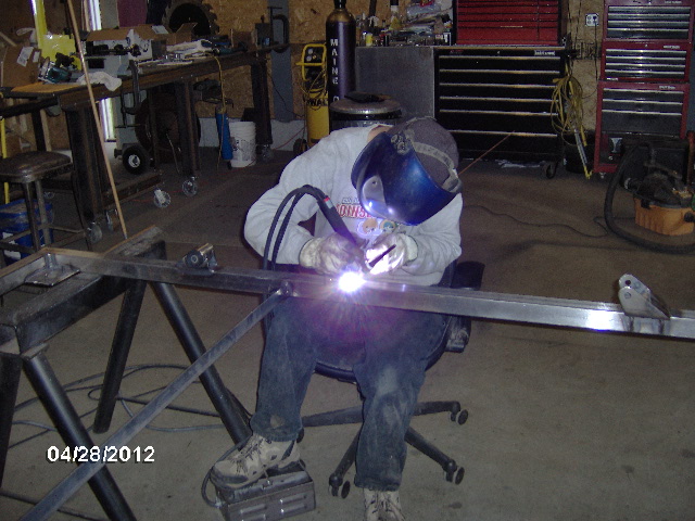
And Karl using his new toy...um, I mean tool.
I guess I didn't get any pics after they were welded, but will do tomorrow. Also in store for tomorrow, now that all of the welding is really complete, will be welding up the little vent holes I drilled (I know, I contradicted myself

), removing the mocked up swivel coupler pintle shaft, and prepping for paint (descaling, a little degreasing, and masking).
All for tonight.
 ... even a steel mesh floor with a high density foam overlay , and a nice rug perhaps ... No wood at all !!!