Ok, here is the AIR PHASE of the heating cooling ceiling system. (passive solar only)
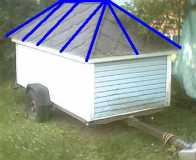
External roof view, with internal beams locations drawn in blue
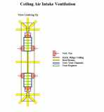
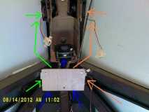
wire frame view of desired summer air flows. (hot air out, cool air in.)
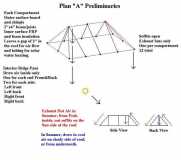
wire frame view of desired winter air flow. (hot air in.)
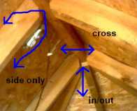
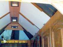
actual internal ceiling view.
additional desired possible air flows. along one side, side to side across, and then from the outside to the inside or inside to outside.
ceiling stained navy blue. vertical view of ceiling where the beams join. (the wire is for the future van spot lights.)
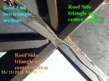
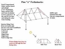
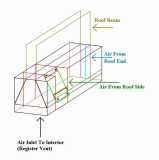
The Design of the air ducting. two end compartments to the end fan, two side compartments to a side fan. roof beams shown.
I was going to do the ducting in the same material used for the inner surface, what is used these days for psuedo-hard-wood-flooring, a highly compressed fiber like material (very dense and hard) but it was too hard to work with so I switched to cardboard and I'll either use that for the patterns of the final pieces or I'll just paint them with polyurethane for water proof and added stiffness. This shows the channeling for the end two sections into the single point, and the separate side triangle sections to get channeled in with their perspective side square areas.
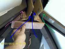
this shows an actual full sized "end cap" in place and the routes of the air flows.
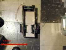
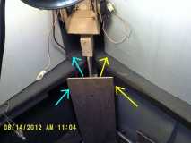
So I needed to make a combining "register box" that had a fan on the end and a fan on each side for input into the register.
(wire frame view.) The box would then be bolted to the center-line beam on top and the bottom would be open for the register/vent.
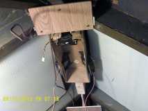
bottom view, assembled with fans.
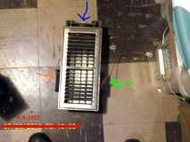
Bottom view, assembled with register in place, 3 air flows displayed.
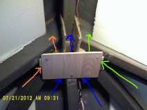
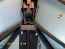
one register box mounted and interfaced with the end ducting, and cap
various air flows diagrammed
A ceiling register cover plate in place and more surrounding air flows diagrammed. This shows just the "along the side" air flow paths. Second box for the other end is installed. Note the divider coming down from the roof center-line beam to restrict the side to side cross ventilation, but just guide the air flows along the individual sides. One will be in the sun and the other in the shade, probably, unless the sun is overhead.
ok, the box at the near end ceiling.
this then is the final view with the registers installed in their cover plates, with the side compartments having their covers in place and the end spot lights installed.
So that is the air flow ducting system.
Next comes either the water system installation (for hot water heating, summer only) or the electronic circuits to automate this entire system. (already built, just not wired in yet.) I'll include a fine breakdown and schematic for anyone who wants to do that wiring themselves, also.


 The interior is looking like a home that you're planning to live in full time!